|
SOLAR WING PANELS
Please use our A-Z INDEX to navigate this site or return HOME
|
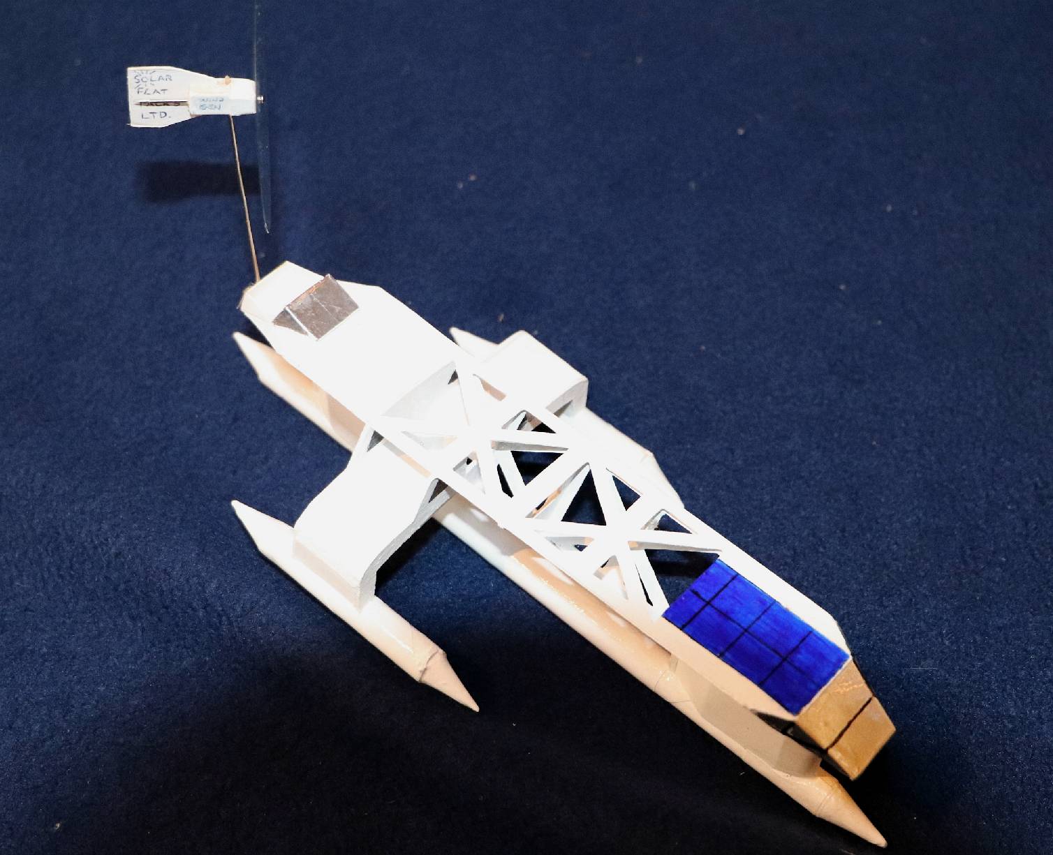
SWATH - It all started with this tiny model, made of paper and cardboard. It floated perfectly as a submerged central hull, with outriggers just skimming the water surface, to provide stability.
In the years that followed a swing wing system and wind turbine boom were developed on a land vehicle. The idea is to combine a rotary sail generator with solar panels to allow faster blue water transits, allied to advanced computer navigation for green lanes.
Most ships have a hull into and onto which, engines, crew and cargo space are fitted, with no thought for harvesting energy from nature. Whereas the sailing ships of old were designed to carry as much sail area as they could. Hence, the Swann is more aligned with the tall ships, than the bunker fuelled smoke belchers of today.
If we are to beat the present water speed record for solar powered vessels, we need to improve on the power to weight ratio and the energy harvesting capacity in relation to solar panel area. How do we do that?
Well, just like the tall sailing ships, we start with the solar panels and wind turbine, working our way back to the water, via an efficient hull.
By incorporating moveable (folding) wings, we can track the sun robotically to increase the apparent solar day, so capturing more energy. It is much like hoisting the top sails in fair weather, and stowing away in storms.
1. A single central submerged hull stabilized by outriggers - or Small Waterplane Area Triple Hull (SWATH).
2. A single central wave piercing hull stabilized by outriggers as a trimaran.
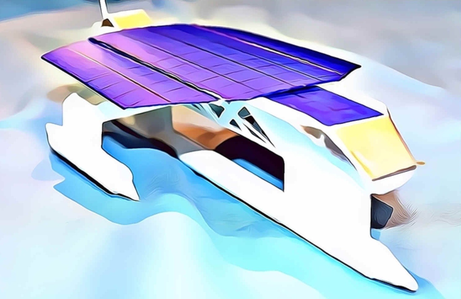
PLAN VIEW - Large solar panel area, defined as three large sections, two being wings that rotate about mounting bearings, with hydraulic motors to turn them to face the sun.
FRONT VIEW - In this CAD drawing we can see that in relation to hull displacement and drag, the solar panel (flat) area is significantly increased with wings, so improving the power to weight ratio.
SUN TRACKING - In this diagram we can see how each wing moves independently of the other, to face the incoming solar radiation (insolation) head on, as far as is possible. For example the port wing only lowers to 33 degrees, to allow clearance for the port sponson. An increase in apparent daylight hours of around 4 hours is possible for the wing area. Unfortunately, the central - hull mounted - panel, does not have this advantage. But can adjust some panels in the fore and aft direction.
FAITHFUL REPLICA - You can see from the 1:200 model, that the CAD version of the proposed design closely resembles the original concept - shown here with the solar panels removed, to reveal the centre section space frame.
Both of the proposed hull designs share the same:
a) Ultra light superstructure purposed designed to harvest energy from nature via b) and c) below,
b) Solar wings that track the sun and fold for storms, in concert with
c) A turbine generator on a mast that tracks wind conditions and furls for storms.
|
|
Please use our A-Z INDEX to navigate this site or return HOME
This website is Copyright © 2021 Jameson Hunter Ltd
|